Scaling in Autocad drawings and layouts.
As you know, no scale is used in AutoCAD drawings. Drawing models are prepared with real dimensions and scale is given during the print-out. In order to do this, print Plot… command is used from File menu. Plot dialog box will appear (Fig.1). You can take print-outs according to the scale you want by setting correct values in mm ve units boxes inside Plot scale part, which is in Plot Settings tab.
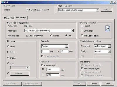 Fig.1
Fig.1
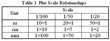
In the example, which is shown in figure, it is set that every 10 units is seen as 1 mm in the print-out, thus 1=10 relation is used. In table.1, you can find plot scale relationships according to several units (m, cm or mm), and scales (1/100, 1/50 veya 1/20) that can be used by the user.
 According to the units and print-out scales chosen by the user, in some cases, print-out may not be at the desired quality. In order to correct the print-outs, some command has to be used or some system variable has to be adjusted to some certain values. These commands and variables are explained hereunder.
Text Height
In general practice, all text should be at a definite height. In order to accomplish that, a certain text height values should be used in the drawing model. These values depend on the units and scales chosen by the user. For example, Text height values that has to be used in the drawing model, to get text height of h=3 mm in the print-out, are shown in Table.2.
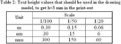 In order to calculate any other h text height, you can multiply the text height values given in table.2 by h/3.
Hatch scale
When Hatch command is called, Boundary Hatch and Fill dialog box appears (Fig.2)
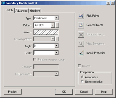 Fig.2 Boundary Hatch and Fill dialog box.
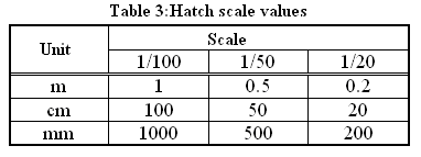
By using various settings in this dialog box, you can change the hatch properties. However, if the value at scale box is not chosen properly, hatch in the print-out may look too dense or too rare. For various units and scales, suggested hatch scale values are given in Table.3.
 Dimscale
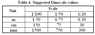
As you know, in order to manage the dimensioning operations in AutoCAD, Dimension menu (or Dim command in the command line) is being used. There are several system variables for modifying the various properties of dimension objects. Among these variables, probably the most important one is Dimscale (dimension scale) variable. In order for the dimension entities to look proper in the print-outs, appropriate values for Dimscale variable is shown in Table.4.
 While drawing is made, as one of the values are set from the table to the Dimscale variable, other system variables can be also modified according to the user’s demands.
Ltscale
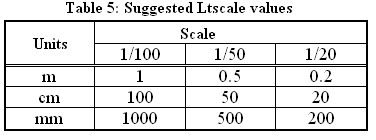
As you know, there are several line types in AutoCAD (dash, dash dot, dot….), if the LTSCALE system variable, which determines how these dashes will look like in the print-out, is not set properly then dashes and dots may look too dense like a continuous line or too rare in the print-out. In order for different line types to show up properly in the print-outs, appropriate values that should be assigned to Ltscale variable are shown in Table.5.
 Editor’s Note: Prof. Günay Özmen is my AutoLISP lecturer during post-graduate study in İ.T.Ü. Architectural Faculty. And he is the first person who planted the concept of AutoCAD customization into our brains. I am proud to say that, I owe him everything that I have accomplished till now, and I appreciate him for writing this article. “Orhan Toker”
 Fig.1
Fig.1In the example, which is shown in figure, it is set that every 10 units is seen as 1 mm in the print-out, thus 1=10 relation is used. In table.1, you can find plot scale relationships according to several units (m, cm or mm), and scales (1/100, 1/50 veya 1/20) that can be used by the user.
 According to the units and print-out scales chosen by the user, in some cases, print-out may not be at the desired quality. In order to correct the print-outs, some command has to be used or some system variable has to be adjusted to some certain values. These commands and variables are explained hereunder.
Text Height
In general practice, all text should be at a definite height. In order to accomplish that, a certain text height values should be used in the drawing model. These values depend on the units and scales chosen by the user. For example, Text height values that has to be used in the drawing model, to get text height of h=3 mm in the print-out, are shown in Table.2.
 In order to calculate any other h text height, you can multiply the text height values given in table.2 by h/3.
Hatch scale
When Hatch command is called, Boundary Hatch and Fill dialog box appears (Fig.2)
 Fig.2 Boundary Hatch and Fill dialog box.
By using various settings in this dialog box, you can change the hatch properties. However, if the value at scale box is not chosen properly, hatch in the print-out may look too dense or too rare. For various units and scales, suggested hatch scale values are given in Table.3.
 Dimscale
As you know, in order to manage the dimensioning operations in AutoCAD, Dimension menu (or Dim command in the command line) is being used. There are several system variables for modifying the various properties of dimension objects. Among these variables, probably the most important one is Dimscale (dimension scale) variable. In order for the dimension entities to look proper in the print-outs, appropriate values for Dimscale variable is shown in Table.4.
 While drawing is made, as one of the values are set from the table to the Dimscale variable, other system variables can be also modified according to the user’s demands.
Ltscale
As you know, there are several line types in AutoCAD (dash, dash dot, dot….), if the LTSCALE system variable, which determines how these dashes will look like in the print-out, is not set properly then dashes and dots may look too dense like a continuous line or too rare in the print-out. In order for different line types to show up properly in the print-outs, appropriate values that should be assigned to Ltscale variable are shown in Table.5.
 Editor’s Note: Prof. Günay Özmen is my AutoLISP lecturer during post-graduate study in İ.T.Ü. Architectural Faculty. And he is the first person who planted the concept of AutoCAD customization into our brains. I am proud to say that, I owe him everything that I have accomplished till now, and I appreciate him for writing this article. “Orhan Toker”
0 comments:
Post a Comment