Introduction to AutoCAD 2009: 5 - VIEW CUBE
Starting with AutoCAD R13, DVIEW, the legendary command, became 3DORBIT in AutoCAD R12 and finally be formed to its most advanced state in AutoCAD 2009. Let us take a look at the form of ‘View Cube’ (Figure 1).

Figure.1 View Cube
To open the view cube, you have to run NAVCUBE command and choose ‘ON’ option. ‘3D Modeling’ have to be used as the workspace for the cube to be opened. Workspaces in AutoCAD 2009 allows ribbon (subject of the first article) to change according to the concept. For instance working in 3D, makes the ribbon equipped with 3D related commands. The last condition to open the view cube is that the view mode have to be any mode but not ‘2D Wireframe’. ‘Realistic’ mode is going to be used in the example figures.
You can do almost everything about view angle once the cube is being opened. Surfaces and corners of the cube is for passing the view angles that were set previously. For example, if you get close to the top right corner of the cube with the mouse, the corner will become active and upon pressing on it, a perspective view from that corner is being shown on the screen (Figure 2).

Figure 2
Corners and edges are placed relatively. So, they are updated according to the new view angle. Yet, FRONT, RIGHT, TOP expressions written on the surfaces implies the same view angle according to the coordinate system. In brief, corners and edges represent the perspective views and the surfaces represent plan views. View cube appearance and attribute also changes automatically with a change in the view mode (Figure 3). When you get the cursor near the cube, four arrows appears which is designed for changing the view modes. There are also circular arrows for rotating the view 90 degrees clockwise or counter-clockwise. The home icon located on the top left corner is for going back to a view mode that is assigned before. You can change the view freely by pressing anywhere on the screen, holding the mouse button and moving the mouse. View Cube is a strong opponent for 3DORBIT which you are going to understand once you get used to it.
 Figure 3
The capability of the cube is equipped generously with the right-click menu. Let us take a look at it (Figure 4).
 Figure 4
* Home: Goes back to your assigned view angle.
* Parallel: Paralell perspective mode.
* Perspective: Real perspective.
Perspective with Ortho Faces: Changes the view of all faces according to the rules of real perspective mode if the current view is not set as plan view.
Set Current View as Home: Stores the current view mode and settings and assigns as ‘Home View’ (Pressing the ‘Home’ icon restores this view).
ViewCube Settings…: opens the cube settings.
A rather big window appears when you press the settings option (Figure 5).
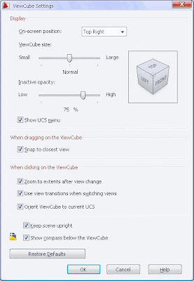 Figure 5
You can edit the size and the opacity (in the passive mode) of the cube via the ‘Display Settings’. Also, the small ‘UCS’ menu below the cube can be turned off here.
‘When Clicking on the ViewCube’ holds a part of the important settings. If you do not want to see any ghosting effects during the view changes unclick the ‘Use view transactions when switching views’ option. The third option is used for locating the cube according to the UCS.
‘Restore Defaults’ button can be used to go back to the default settings which are the most suitable ones, I guess.
Compaerd with the 3DORBIT, the single disadvantage of the VIEW CUBE, which we examined in detail, is that the front and back of the view is being clipped. Yet, 3DCLIP command works much better compared to the previous one.

Figure.1 View Cube
To open the view cube, you have to run NAVCUBE command and choose ‘ON’ option. ‘3D Modeling’ have to be used as the workspace for the cube to be opened. Workspaces in AutoCAD 2009 allows ribbon (subject of the first article) to change according to the concept. For instance working in 3D, makes the ribbon equipped with 3D related commands. The last condition to open the view cube is that the view mode have to be any mode but not ‘2D Wireframe’. ‘Realistic’ mode is going to be used in the example figures.
You can do almost everything about view angle once the cube is being opened. Surfaces and corners of the cube is for passing the view angles that were set previously. For example, if you get close to the top right corner of the cube with the mouse, the corner will become active and upon pressing on it, a perspective view from that corner is being shown on the screen (Figure 2).

Figure 2
Corners and edges are placed relatively. So, they are updated according to the new view angle. Yet, FRONT, RIGHT, TOP expressions written on the surfaces implies the same view angle according to the coordinate system. In brief, corners and edges represent the perspective views and the surfaces represent plan views. View cube appearance and attribute also changes automatically with a change in the view mode (Figure 3). When you get the cursor near the cube, four arrows appears which is designed for changing the view modes. There are also circular arrows for rotating the view 90 degrees clockwise or counter-clockwise. The home icon located on the top left corner is for going back to a view mode that is assigned before. You can change the view freely by pressing anywhere on the screen, holding the mouse button and moving the mouse. View Cube is a strong opponent for 3DORBIT which you are going to understand once you get used to it.
 Figure 3
The capability of the cube is equipped generously with the right-click menu. Let us take a look at it (Figure 4).
 Figure 4
* Home: Goes back to your assigned view angle.
* Parallel: Paralell perspective mode.
* Perspective: Real perspective.
Perspective with Ortho Faces: Changes the view of all faces according to the rules of real perspective mode if the current view is not set as plan view.
Set Current View as Home: Stores the current view mode and settings and assigns as ‘Home View’ (Pressing the ‘Home’ icon restores this view).
ViewCube Settings…: opens the cube settings.
A rather big window appears when you press the settings option (Figure 5).
 Figure 5
You can edit the size and the opacity (in the passive mode) of the cube via the ‘Display Settings’. Also, the small ‘UCS’ menu below the cube can be turned off here.
‘When Clicking on the ViewCube’ holds a part of the important settings. If you do not want to see any ghosting effects during the view changes unclick the ‘Use view transactions when switching views’ option. The third option is used for locating the cube according to the UCS.
‘Restore Defaults’ button can be used to go back to the default settings which are the most suitable ones, I guess.
Compaerd with the 3DORBIT, the single disadvantage of the VIEW CUBE, which we examined in detail, is that the front and back of the view is being clipped. Yet, 3DCLIP command works much better compared to the previous one.


