Topics covered in this Lesson:Rectangle | Multi Line | Extend | Offset | Trim |
Introduction to Object Snaps
The previous lesson dealt with drawing commands. This lesson will introduce the common modifying commands. In AutoCAD, you may actually use modifying commands more often than drawing commands. Now that you know that basics, here's some more commands to add to your collection. Three commands, Trim, Extend and Offset are used standard AutoCAD work.
 Assignment #2 - Modifying Commands
The purpose of this assignment is to use the commands learned in the previous lesson and learn some new ones.
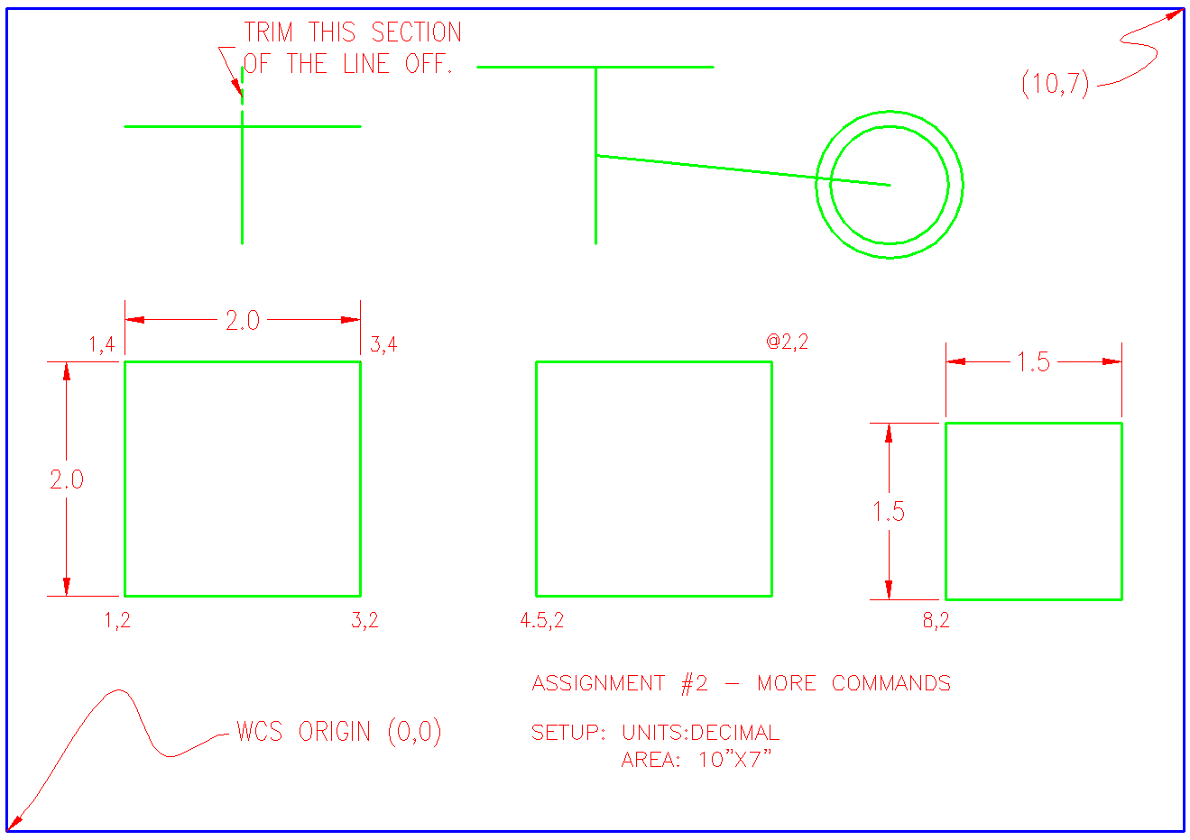
Duplicate the drawing called
Assign_2.Click
HERE to download the DWG file.
Once again, do not worry about title blocks, text or dimensions, draw only what is in yellow.
Start AutoCAD and begin the the drawing by opening up the template file like you did in
Draw a
LINE from
1,2 to
3,2 to
3,4 to
1,4 (*
Remember to watch the command line as you do this.) For the last line, you can either type in 1,2 or C to close the line back to the first point you entered. These are
absolute co-ordinates. Make sure you understand what the points your just entered represent.
Draw the next square using the
RECTANGLE command. A rectangle is created by specifying 2 points to represent the opposite corners. Enter the first point as
4.5,2 and then make the opposite corner 2 inches over and 2 inches up
@2,2 using
relative co-ordinates. This is much faster and also makes the square
one object and not 4 separate lines.
ERASE the rectangle. You will see that all of it is gone with
one pick. Redraw it and continue.
Draw the third box using the
MULTILINE command. This box is 1-1/2" square. The following steps are what you will see on the command line. Before drawing the lines, you have to set the SCALE to 0.15"(distance between the lines) by typing 'S'. Then set the JUSTIFICATION (offset origin) by typing 'J'.
Command:
ml MLINECurrent settings: Justification = Top, Scale = 1.00, Style = STANDARDSpecify start point or [Justification/Scale/STyle]: s Enter mline scale <1.00>: .15Current settings: Justification = Top, Scale = 0.15, Style = STANDARDSpecify start point or [Justification/Scale/STyle]: 8,2 Specify next point: @1.5,0 Specify next point or [Undo]: @0,1.5 Specify next point or [Close/Undo]: @-1.5,0 Specify next point or [Close/Undo]: @0,-1.5 Specify next point or [Close/Undo]: To review what you just did, you started the command, then set the scale (distance between the lines) to .15 units. Then you just drew the rectangle using relative co-ordinates.Erase the multiline rectangle you just drew. Notice that when you hover over the rectangle, it will turn to a dotted line. This means that it is highlighted as the object that will be selected if you pick at that moment. In highly detailed drawings, this is very handy.Draw it again as shown below and note the subtle difference from the first one you drew.Command: ML MLINECurrent settings: Justification = Top, Scale = 1.00, Style = STANDARDSpecify start point or [Justification/Scale/STyle]: s Enter mline scale <1.00>: .15Current settings: Justification = Top, Scale = 0.15, Style = STANDARDSpecify start point or [Justification/Scale/STyle]: 8,2 Specify next point: @1.5,0 Specify next point or [Undo]: @0,1.5 Specify next point or [Close/Undo]: @-1.5,0 Specify next point or [Close/Undo]: C The difference is that instead of drawing to the last point, you used the C (close) option to complete the rectangle. The difference is shown in the drawing below.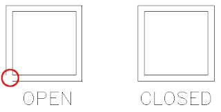
This is an example of why you have to look at the command line as you work. As soon as you start the command, you have choices available. Whenever you see this come up, if you want to change anything, you just type the
CAPITAL letter of the option. For example, if you want to undo the last point, you would type
u at this point. For this assignment you only changed the scale. After you have completed the assignment, try different settings for this command. Use your AutoCAD
help option to see what these options control. (NOTE: I don't normally use Multilines while drawing as I don't have complete control over both the inner and outer lines. On the other hand, Multilines can be great for drawing quick offset lines. Also, they cannot be trimmed (you have to explode them first).
Draw a line from
2,5 to
2,6.5 Draw another line from
1,6 to
3,6 You should now have two perpendicular lines. What you want to do is trim off the top of the vertical line and create a T.
Start the
TRIM command. It will first ask for a cutting edge. Select the horizontal line and press
. It will now ask for the object to be trimmed. Select the vertical line anywhere above the horizontal (cutting) line and press to finish the command.This is what you saw on the command line:Command: TR TRIMCurrent settings: Projection=UCS, Edge=NoneSelect cutting edges ...Select objects: <Select the Horizontal line>1 foundSelect objects: <enter>Select object to trim or shift-select to extend or [Fence/Crossing/Project/Edge/eRase/Undo]: <Select the vertical line>Select object to trim or shift-select to extend or [Project/Edge/Undo]: <enter>Once again, it is important to keep your eye on the command line as it will guide through most commands.Draw a LINE from 4,6.5 to 6,6.5 Draw another line from 5,5 to 5,6 What you want to do now is extend the vertical line up to the meet horizontal line. Start the EXTEND command. AutoCAD asks for a boundary edge; select the horizontal line press . It then asks for an object to extend; select somewhere in the top half of the vertical line. Press to end the command. Your command line history should match what is printed below.Command: EX <enter> EXTENDCurrent settings: Projection=UCS, Edge=NoneSelect boundary edges ...Select objects: <Select the horizontal line> 1 foundSelect objects: <enter>Select object to extend or shift-select to trim or [Fence/Crossing/Project/Edge/Undo]: <Select the top half of the vertical line>Select object to extend or shift-select to trim or [Project/Edge/Undo]: <enter>Draw a CIRCLE with a center point of 7.5,5.5 with a radius of .5 Now you will use to offset command to make another circle 1/4" larger. Start the OFFSET command (watch the command line) and enter .125 as the offset distance. Now select the circle and pick anywhere outside the circle. Press to end the command.Object Snaps
Suppose you want to draw a line from the center of the circle to the middle of the vertical line you extended earlier. AutoCAD has a feature that makes this very easy. These are the Object Snaps (or Osnaps "Oh-Snaps"). Type
OS . You will see this dialog box appear.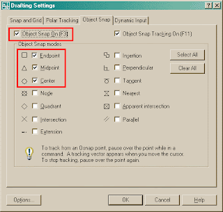
You may also see a toolbar with these Osnaps as shown below.


You may select whichever points you want to 'snap' on an object. Here is a list of your options. Followed by the command entry to invoke the needed Osnap.
Endpoint - snaps to either the beginning or the end of an object such as a line -
ENDMidpoint - snaps to the exact middle of a line or an arc -
MIDCenter - snaps to the center-point of a circle or arc -
CENNode - snaps to 'nodes' (not covered in this course) -
NODQuadrant - snaps to any of the four quadrants of a circle -
QUAIntersection - snaps to the point where two object cross -
INTExtension - Snaps to the phantom extension of an arc or line -
EXTInsertion - snaps to the insertion point of an object (such as a block or text) -
INSPerpendicular - will snap so that the result is perpendicular to line selected -
PERTangent - snaps to create a line tangent to a circle or arc -
TANNearest - will find the closest point an object and snap to that point -
NEAParallel -Snaps parallel to a specified line -
PARNone - temporarily turns off all Osnaps. (Pressing your F3 Key is quicker) -
NONOsnap settings - opens the Osnap dialog box.
Temporary Tracking - Creates a temporary tracking point (see Object Tracking).
From - Allows you to select a point, then denote a new location 'from' that point using relative co-ordinates. This can save you the time of drawing (and erasing) construction lines.
M2P - This isn't technically an 'Object Snap' as you are not snapping to an object, but it allows you to select 2 points and it will calculate the midpoint between those 2 points. This is a very handy option to have.
Note: Beside each checkbox is a symbol. That symbol will show up on the screen when you have found a valid snap point. (An endpoint will show a small square). If you select the "Options" button, you can change the aperture size and the color of the Osnaps. Depending upon the background you are drawing on, this may be needed.
1.Check off the boxes as shown in the dialog box above (Object Snaps On, Endpoint, Midpoint, Center) and press
OK.2.Begin the
LINE command. Move your cursor around the screen and you'll see that as you get close to an object, it will 'snap' to one of the points that you had checked off in the dialog box. Place your cursor on the circle (not the middle of the circle) until you see a small purple circle appear at its center. Left-click to make this the start point of the line. Move the cursor towards the middle of the vertical line until you see a small triangle appear. (Remember this is the symbol for 'midpoint'). When you see it left-click to accept this as your endpoint. Press to end the line command.
3.Save your drawing.
4.Print your drawing with the same settings as in
Assignment #1.TIP: Before you select the Osnap you want, you can press the TAB key on your keyboard to cycle through the available Osnaps in the area of your cursor.
CAUTION: Although it may seem tempting to turn 'all' the Osnaps on when drawing, you can have too much of a good thing. For example, in shorter lines, Midpoint, Nearest and Perpendicular could all be very close to each other, and you could select the wrong point.
When you have finished the assignment, continue practicing with the commands until they are mastered. These are common commands that you will use in everyday drafting.
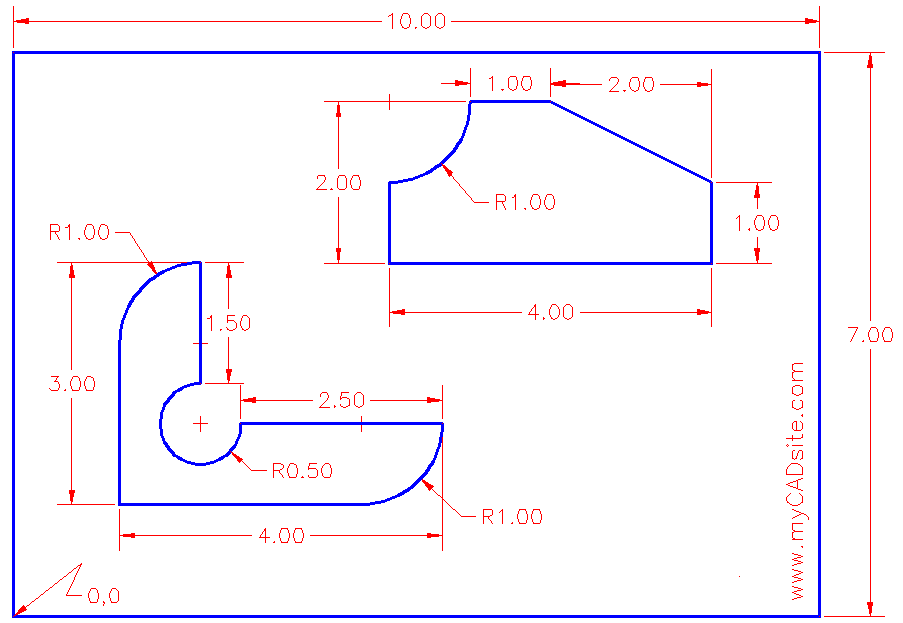
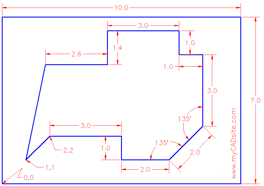
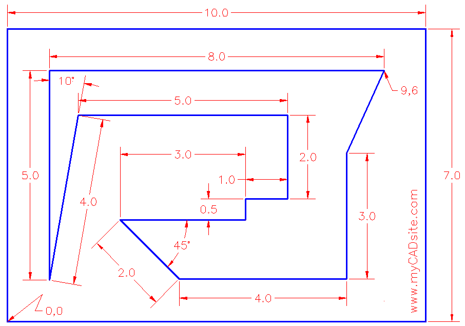
Extra Practice: Copy this drawing, using lines, mlines, offset, osnaps -
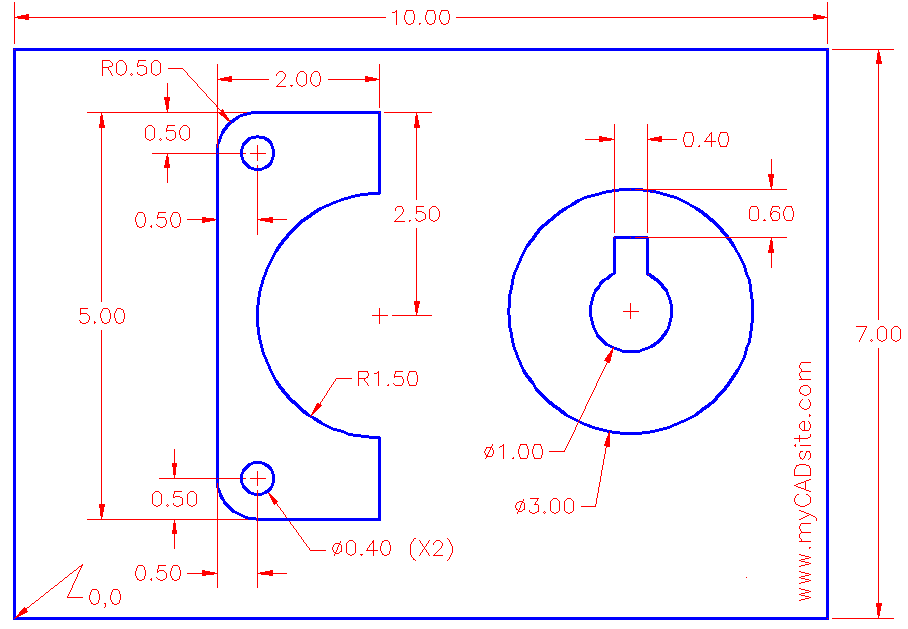
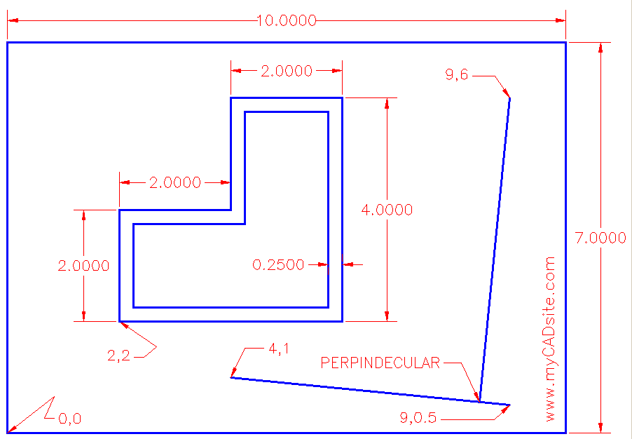
extra_003.gifExtra Practice: Copy this drawing, it could a little to figure out, but still uses the commands you have learned so far. -
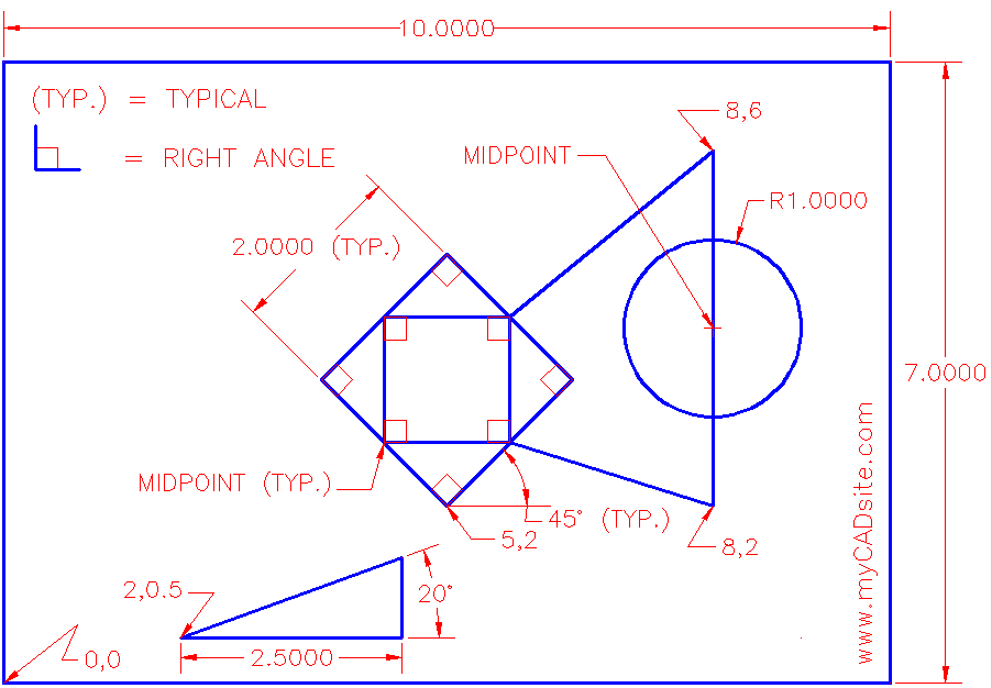
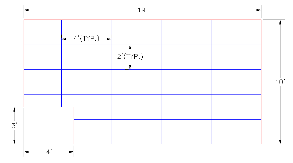
extra_004.gifExtra Practice: Have a look at
this drawing of a simple reflected ceiling plan (RCF) and see how the offset, trim and extend commands might be used. If you know how to change units to Architectural, try drawing it.


 As you can see there are quite a few options. To begin with I would strongly recommend getting really good at these 3: