A solid modeling application: Gusket drawing
Due to the fact that Erhan Toker cannot make the example of gasket drawing that he has given in his live sections article :) , he just said that Orhan will do it. Indeed, as I made the drawing and gave him, I will show the application. We have taken the drawing for 3 dimensional example from book of our teacher Prof. Mustafa Alışverişçi from Yıldız Technical University (İstanbul-1989.edition) Figure II. (see Fig. 1)
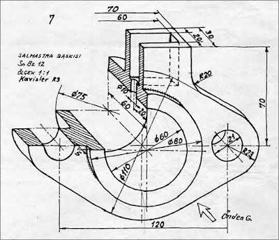 Fig.1 Technical drawing for the part for which we will make solid modeling.
As we are trying to make 3 dimensional modeling from the technical drawing, I assume that you can read the drawing and proceed with the application. Let’s start by drawing the axis lines and circles that make up the boundaries (Fig. 2).
 Fig.2 Model, axis and boundary circles of which was drawn.
Then, let’s draw the tangent lines for the adjacent circles (LINE tan tan). You can either repeat this process for four sides, or you can make one of them and make mirror of it with respect to one axis first and then again mirror it with respect to other axis. After the lines are completed, then form up the complete frame by using TRIM command to trim the leading edges of the lines (Fig. 3).
 Fig.3 View after completing trim of leading edges.
Now, let’s make up the upper side of out part. After making our horizontal axis OFFSET by 70 units up and down and vertical axis 35 units left and right, make necessary trims, and our frame is completed. Don’t forget to make the R20 radius at the location where the upper side is connected to the body (Fig. 4). Fig.4 As the upper side is also completed and converted to POLYLINE
 Fig.4 Upper side is completed
Then, convert this external frame that you have drawn into POLYLINE by using PEDIT+JOIN and go to perspective view by using VPOINT command (Fig. 5). Now, we can proceed with solid modeling. At this stage, don’t forget that you should have some UCS knowledge.
 Fig.5 Isometric view
First thing to do is to extrude the entity that will have just completed and converted into POLYLINE which will be the main body of our model. In order to do these, you have to open the “Solids” and “Solid Editing” toolbars. Now, let’s give some height to the POLYLINE. Use the “Extrude” option from “Solids” toolbar and select the entity. Enter 30 for height and continue over the other questions. Then, you will obtain what is shown in Fig. 6.
 Fig.6 We obtained the first solid by using EXTRUDE command.
Now, let’s make the holes at two sides of the part. Draw one number of circles with 21 diameter to each of the axis and EXTRUDE then by 30 units as explained above. Then, extract these two cylinders from the body by using “subtract” from “Solid Modify” toolbar (Fig. 7). SUBTRACT command is quite simple. First, you will select the body and then select the entities that will be subtracted.
 Fig.7 Let’s open the holes by using SUBTRACT command.
Before the part will get complicated, let’s prepare the oil chamber and subtract it from the main body. You can either draw this shape in another place and move it to its location, or directly draw it at its location. In order to test you UCS knowledge, I will draw it in its own location. First, rotate the UCS 90 degrees around X axis. You will execute the command as UCS / x / 90. Now, you will see that your cursor will become parallel to the rectangular face on the upper side of the part. Let’s draw a 60×20 rectangle on the corner and place it in the middle by using MOVE command. If you pay attention, you can see that you can enter coordinates for drawing the rectangle and the MOVE command as if you are drawing in the ground plane. Draw the lower left corner of the rectangle by using the lower left corner of the face as reference and you will notice that it is done with the command that you are already familiar with (Fig.8).
 Fig.8 Let’s start opening a hole on the rectangular inlet by rotation UCS around X axis.
Now, let’s EXTRUDE the rectangle by 30 units. Now, it’s time to make the oil opening. Hole has 10 radius and has a depth same as of wall thickness of shaft opening, which is 10. Let’s add it now. First, draw a circle with 5 radius in the lower middle of the front of rectangle and shift it by using MOVE command. As you have placed the circle in the middle now, you can the circle by 15 units and then combine it with the rectangle box by suinEXTRUDEg UNION from “solid editing” toolbar (Fig. 9).
 Fig.9 Inlet opening of Oil chamber, let it be on the side…
You can set your UCS back to its original buy using UCS / w. We are almost finished. Let’s complete the part by making the shaft opening in the middle. Let’s draw a circle with 80 radius and make it higher by 60 units. Then, let’s carry this cylinder, which will be the outlet opening of shaft opening to its location. MOVE 0,0 and @0,0,-25. As you can see, I moved this cylinder 25 units in z axis without moving it in x and y directions. Now, let’s make UNION to merge this cylinder with the main part. You should draw one more cylinder to make the opening in the middle. You can draw it your self by the same method as I described above. Then, SUBRACT it from the main body. You can also SUBTRACT the layer, which we have prepared previously, that represents the oil chamber and hole from the main body (If you did it ad that time, then there wouldn’t be any holes on the shaft opening). Fig. 10.
 Fig.10 Finally completed model.
0 comments:
Post a Comment