3D Modeling: Drawing a 3D Bearing in 15 minutes
You’ll comprehend drawing a simple 3D bearing with standard dimensions by using REVOLVE and 3DARRAY commands. All dimensions of our drawing is free.
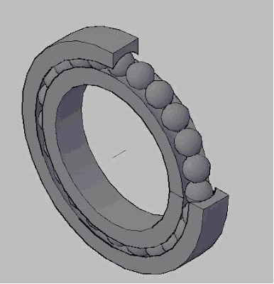 Figure.1 The final view of the bearing.
First of all, we have to draw the 2D object in the figure below. The pint here is it must be polyline. You can draw it with lines and then modify it by PEDIT command.
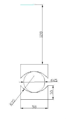 Figure.2 The 2D Figure to construct our bearing.
The blue line in the figure which has an important role in drawing the rest is the axis of our bearing. After completing the drawing, switch to SW isometric view and REVOLVE the figure.
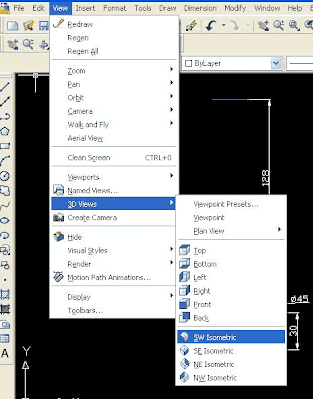 Figure.3 Switching to Isometric View
Command:_revolve Select objects to revolve: (Select the inner section)
Select the inner section.
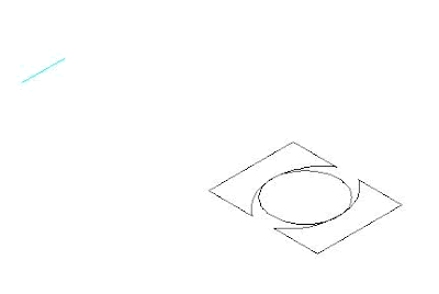 Figure.4 Typical wiew during Revolve command
Specify axis start point or define axis by [Object/X/Y/Z] Specify our axis.
Define the axis by implying the endpoints of our blue line.
Specify angle of revulation or [STart angle] <360>: Revolve Angle
Press ‘ENTER’ to 360 default.
Now, let us utilize SPHERE command to construct our balls
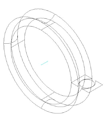 Figure.5 The Completed Bearing Skeleton
Command: Sphere
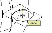 Figure.6 The selection of center and quadrant
To construct one of our balls, click the center of the circle and then the quadrant. We are going to use 3DARRAY command to get 23 of those balls.
Command: 3darray Select Objects: Select our sphere and press ‘ENTER’. Enter the type of array [Rectangular / Polar] : Type ‘P’ and press ‘ENTER’. Enter the number of items in the array: type ‘23’ and press ‘ENTER’. Specify angel to fill (+=ccw, -=cw) <360>: Press ENTER. Rotate arrayed objects? [Yes/No] : Press ‘ENTER’. Specify center point of array: Specify the axis. Pick the endpoints of the blue line.
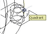 Figure.7 You should see a figure like above if you have done everything correctly.
Let us now REVOLVE our last part.
Command:revolve Select objects to revolve: Select the outer part. Specify axis start point or define axis by [Object/X/Y/Z] : Pick the endpoints of the blue line. Specify angle of revulation or [STart angle] : Type ‘270’ and press ‘ENTER’.
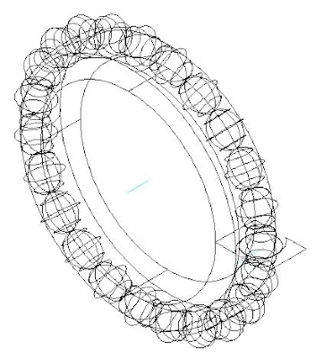 Figure.8 The final state of our model
If you have done all processes mentioned above, you would get a model like the one above. You can check it out in shaded mode by typing ‘SHADE’ and press ‘ENTER’.
Those who are using version 2007 can get the figure above by pressing ‘Conceptual‘ Visual Style.
Regards.
 Figure.1 The final view of the bearing.
First of all, we have to draw the 2D object in the figure below. The pint here is it must be polyline. You can draw it with lines and then modify it by PEDIT command.
 Figure.2 The 2D Figure to construct our bearing.
The blue line in the figure which has an important role in drawing the rest is the axis of our bearing. After completing the drawing, switch to SW isometric view and REVOLVE the figure.
 Figure.3 Switching to Isometric View
Command:_revolve Select objects to revolve: (Select the inner section)
Select the inner section.
 Figure.4 Typical wiew during Revolve command
Specify axis start point or define axis by [Object/X/Y/Z] Specify our axis.
Define the axis by implying the endpoints of our blue line.
Specify angle of revulation or [STart angle] <360>: Revolve Angle
Press ‘ENTER’ to 360 default.
Now, let us utilize SPHERE command to construct our balls
 Figure.5 The Completed Bearing Skeleton
Command: Sphere
 Figure.6 The selection of center and quadrant
To construct one of our balls, click the center of the circle and then the quadrant. We are going to use 3DARRAY command to get 23 of those balls.
Command: 3darray Select Objects: Select our sphere and press ‘ENTER’. Enter the type of array [Rectangular / Polar] : Type ‘P’ and press ‘ENTER’. Enter the number of items in the array: type ‘23’ and press ‘ENTER’. Specify angel to fill (+=ccw, -=cw) <360>: Press ENTER. Rotate arrayed objects? [Yes/No] : Press ‘ENTER’. Specify center point of array: Specify the axis. Pick the endpoints of the blue line.
 Figure.7 You should see a figure like above if you have done everything correctly.
Let us now REVOLVE our last part.
Command:revolve Select objects to revolve: Select the outer part. Specify axis start point or define axis by [Object/X/Y/Z] : Pick the endpoints of the blue line. Specify angle of revulation or [STart angle] : Type ‘270’ and press ‘ENTER’.
 Figure.8 The final state of our model
If you have done all processes mentioned above, you would get a model like the one above. You can check it out in shaded mode by typing ‘SHADE’ and press ‘ENTER’.
Those who are using version 2007 can get the figure above by pressing ‘Conceptual‘ Visual Style.
Regards.
0 comments:
Post a Comment