3D Modeling Application: Drawing a 3D rim
Today, we are going to draw a 3D Rim. The reason for doing a 3D one is that the interest in modelling subject. We have a rim like the one in Figure 1. Let us start with drawing the shape in given dimensions. (The radius values are all 1 mm if not specified)
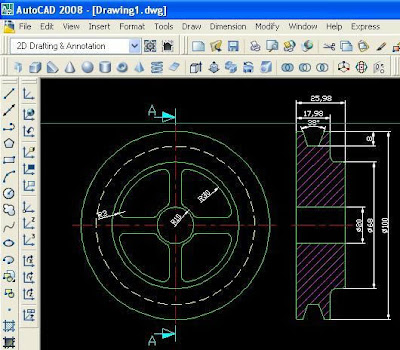 Figure 1 - Detailed Figure of the Rim
Now, copy the 100-diameter circle and switch to View>3D Views>SW isometric view. By the way, there are lots of bloggers having difficulties with UCS. Let me mention a practical method which I also use. Draw a square and EXTRUDE it when you are in SW isometric view.
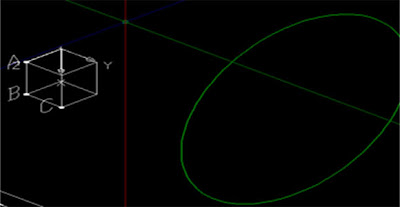 Fig.2
Fig.2
The marked points ‘a-b-c’ are our selection points for UCS. Select the 3 points option of UCS command. By selecting the ‘a-b-c’ points in order, you can do any process in that plane. This method is also valid for other planes including inclined ones.
Our job is very easy since our object is symmetrical. Draw the upper part seen above the axis of the section view of the object as PLINE as it can be seen in the figure below. You must get the exact same figure like the one below.
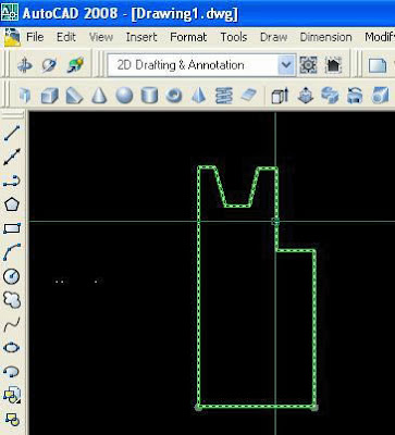 Fig.3
Fig.3
Now, we will almost constitute our rim with a single command called REVOLVE. Type revolve in the command line and press enter, then select the parts and choose the points seen below and a preview must be appeared. And our rim is ready. We will make the holes seen in front view. Click Views>3D>NE isometric and coming figure must be as below.
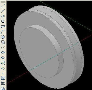 Fig.4
Fig.4
Draw the flange form exactly like the one below. You can draw either in 2D or 3D mod. Join the body cuts on the flange with pedit>join command. Repeat same steps for all 4 cuts. Turn the Dimension and Axis layers off and switch the View>Sw izometric for the flange.
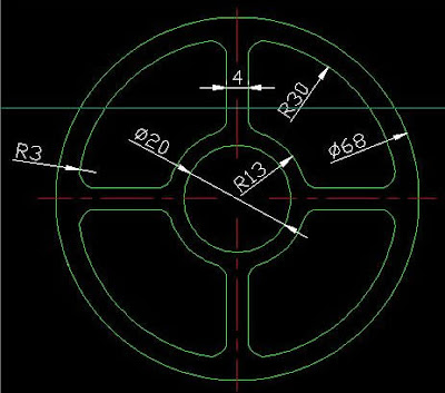 Figure 5 – Drawing of the Flange of the Rim
EXTRUDE the outer diamater and body cuts in the isometric view. You can extrude 8mm. After the ‘extrude’ process, move the flange from its back center to the rim and join them with UNION command. During the UNION process do not include the body cuts and center hole otherwise you can not SUBTRACT.
Combine the flange with the rim (UNION) , take the body cuts and the hole out from the sketch and our rim is prepared. Mat it be easy..
 Figure 1 - Detailed Figure of the Rim
Now, copy the 100-diameter circle and switch to View>3D Views>SW isometric view. By the way, there are lots of bloggers having difficulties with UCS. Let me mention a practical method which I also use. Draw a square and EXTRUDE it when you are in SW isometric view.
 Fig.2
Fig.2The marked points ‘a-b-c’ are our selection points for UCS. Select the 3 points option of UCS command. By selecting the ‘a-b-c’ points in order, you can do any process in that plane. This method is also valid for other planes including inclined ones.
Our job is very easy since our object is symmetrical. Draw the upper part seen above the axis of the section view of the object as PLINE as it can be seen in the figure below. You must get the exact same figure like the one below.
 Fig.3
Fig.3Now, we will almost constitute our rim with a single command called REVOLVE. Type revolve in the command line and press enter, then select the parts and choose the points seen below and a preview must be appeared. And our rim is ready. We will make the holes seen in front view. Click Views>3D>NE isometric and coming figure must be as below.
 Fig.4
Fig.4Draw the flange form exactly like the one below. You can draw either in 2D or 3D mod. Join the body cuts on the flange with pedit>join command. Repeat same steps for all 4 cuts. Turn the Dimension and Axis layers off and switch the View>Sw izometric for the flange.
 Figure 5 – Drawing of the Flange of the Rim
EXTRUDE the outer diamater and body cuts in the isometric view. You can extrude 8mm. After the ‘extrude’ process, move the flange from its back center to the rim and join them with UNION command. During the UNION process do not include the body cuts and center hole otherwise you can not SUBTRACT.
Combine the flange with the rim (UNION) , take the body cuts and the hole out from the sketch and our rim is prepared. Mat it be easy..

1 comments:
This software is useful for many fields like Engineering, Architecture, Arts, Fashion Technology etc. Browse for Autodesk Products for more Information.
Solidworks Course
Post a Comment